 45 horsepower for Dominion Gov for
Locks >>Peterborough Lift Lock >>
----
Ragged Chutes = 5,500 h.P with 1,000 hp reserve ------
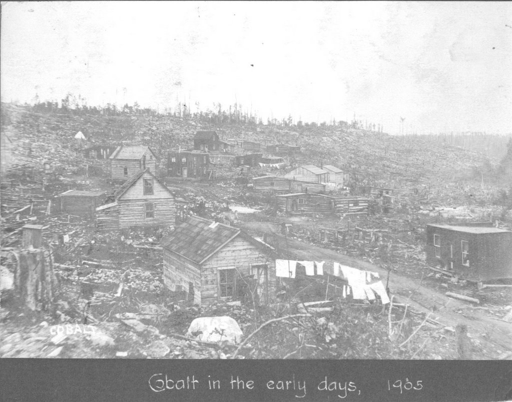
COBALT , ONTARIO visited in 1905 and plant completed in 1910
During the 1930's, the Tennesseee Valley Authority, using Taylor plans, built a 50,000 H.P. plant. One of the designers misread a measurement by a decimal point and plant efficiency was reduced to 10%. This illustrates how accurate the original Taylor design had been.
----------------------
God, so many ideas... Look at this lock setup,, Am i just stupid or cant we just simply fill lifts and weight of water can push down onshafts and move gears or other mediums to turn turbins...
Air, Dirty Water, Oil, etc...
Weight down and then doors or valves open and let out water to go on and the other side fills and lowers..??
AND JUST USE SHIPS as quick launch platforms of variuos sizes
We could launch 5 to 10 projects of various interests and designs....


We can sell the cost of Electriity to Industry and guarantee them it will always be cheaper... we keep excess and they buy by annual allotment... we keep excess...
But we get to gain knowledge in new understandings in performance in Hydrogen Gas, Cavatation, Ice, Under Ice Flows, Fish, We lease out space and area and sell data around the world..
--600 foot wide dam can be achieved as ship is 1,000 feet and we can flow back to each side as it is a tide....
We could use a tanker as the 1,021 foot long 20 W X 26 H then to 42 feet high tunnel to store air for offtake.....but how do we duplicate the 352 foot X10 foot diameter water fall shaft. > Maybe use four (4) 10 foot diameter shafts.????
 Google map of Kaslo, BC museum
http://maps.google.com/maps?hl=en&tab=wl&q=kaslo%20bc
In 1901 a Fourth compressor was built in the State of Washington. Then in 1906, a general purpose compressor was constructed in Norwich Connecticut. That same year Taylor was commissioned to build a 550 Horsepower compressor for the Victoria Copper Mine in Rockland Michigan which delivered air at 117 p.s.i. Other plants were built in Tarica, Peru and in Germany.The largest and most ambitious Air Plant was the Ragged Chutes plant at Cobalt Ontario. Taylor visited Cobalt in 1905 and determined that the conditions and the mining industry were ideally suited to his invention. Work on the plant was completed in 1910.
------------------------------------------------------
-------------------
Can we use a wind turbine mast as piping, or concrete make on spot.. on location, or large culverts--Is there a piece we can use that works in all applications...over and over again??
-----------------------------------------------------------------------------------------
 creek. The air was piped two to three miles to mines as far away as the "United" until about 1910. The "BC Mining Record" of September 1906 carried a detailed description of this plant. One would have anticipated a huge market for this compression device, but it was said that the process leached most of the oxygen out of the air, with the result that the oxygen-starved compressed air piped into underground passages was lethal to workers. This could account for the poor performance of the Taylor Air Compressor in the market." A photograph of the compressor on page 2 is captioned with a statement saying that the compressor collapsed in 1916. See also Page 49
 1905 - 1910 The building of Ragged Chutes
 Ragged Chutes was Charles most ambitious project and his greatest success. The feeder shaft, 351 feet deep and 9 and 1/2 feet in diameter was sunk into the bedrock. The lower 40 feet widens to 11 and 1/2 feet in diameter. At the top of this shaft are twin intake heads each containing 72 intake pipes, 16 inches in diameter.Water backed up behind the 660 foot wide dam swirls down through these pipes carrying air with it. When the water reaches the bottom of the shaft, it is diverterted into a 1021 foot long horizontal tunnel by a steel sheathed concrete cone.
------------------------------------------------------------------------------------------------ using lift locks for water stop and go, lay down the fall Horizontaly will require how much more in length to get same water pressure as Verticle Fall Flume ??
 TIDAL ?
1877 J.P. Frizell 5' fall and 36' shaft
1896 C.H. Taylor
Magog, Quebec
3 patents by Taylor
1896, 1898, 1900
hydraulic air compressor
http://charleshtaylor.blogspot.com/
In 1895 while building a dam in Buckingham Quebec Taylor noticed that air bubbles that were trapped in the water as it flowed over the spillway were carried under the ice and formed ice domes. When he broke one of the domes with a pipe he realized that the air was pressurized. Insignificant as this may appear to some, Taylor's mind was quick to grasp the industrial possibilities of this phenomenon. He made a working model of a compressor in a warehouse in Montreal. Glass tubing was integrated int the model so that all could see the operation of the machine and as experiments progressed modifications could be made to enhance efficiency
---------------------------------------------------------------------------------------------- http://wikimapia.org/6876736/Ragged-Chute-The-World-s-Only-Water-Powered-Compressed-Air-Plant
There is a GOOGLE View of the site at this site above
Ragged Chute - The World's Only Water Powered Compressed Air Plant
At Ragged Chute, 16 km southeast of Cobalt on the Montreal River, stands the world's only water-powered compressed air plant.
Built in 1910, at the peak of the Cobalt silver boom, Ragged Chute Compressed Air Plant transmits air-power to the local mining industry.
Compressed air, rather than electricity, is the main power source used by heavy mining equipment such as drilling machines, grinders and hoists.
Today, though, most mines purchase electricity to run their own air compressors. Since it was built in 1910, Ragged Chute has practically run itself. While under construction, in the early years of this century, a community of workers did live on the site.
In 1945, Ontario Hydro purchased the Ragged Chute plant and continues to supply local mines with the compressed air created there.
------------------------------------------------------------------------------------------
July/August 1977 http://www.motherearthnews.com/Renewable-Energy/1977-07-01/Harness-Hydro-Power-with-a-Trompe.aspx
 Image Gallery Enlarge Image
Ragget Chutes Trompe Power
 http://www.motherearthnews.com/
Renewable-Energy/1977-07-01/Harness-Hydro-Power-with-a-Trompe.aspx
http://charleshtaylor.blogspot.com/
/2009/02/
hydraulic-air-compressor-brief-history.html
Catalan blast forges
Hydraulic air blasts for forges >>
Hydraulic air compression plants --1977 Ragged Chutes.. Canada
IDEA = Why cant we use the city water lines -- 3" mains...? in several places around town we install water wheel generators or water pushing air.. how many generators can we handle in the lines before they lose power -- how many times can we genrerate
Production was 1oz, 0unce to to 1 pound per square inch.........
http://www.motherearthnews.com/Renewable-Energy/1977-07-01/Harness-Hydro-Power-with-a-Trompe.aspx
-------------------------------------------------------------------------------
Sullivan -Corliss steam engines
Corliss steam engines -- only ?
Rand Drill Co....??
Ingersoll-Seargent
ASME call 1- 212- 591-7020
I want to look for the small units of air compression by water pressure---
small Water Pressure Compressors
Johnson Service Company
Warren S Johnson ( 1845 - 1911) found compressed air to be
His 1895 system was completely mechanical Operating off of compressed air that used city water pressure.
May 1st, 1885 Johnson Electric Service Co. a Wisconsin company ( 40 years old) Milwakee
http://www.blogger.com/post-edit.g?blogID=1726383692447715062&postID=1950257843510663120
-------------------------------------------------------------------------------------------------
http://books.google.com/books?hl=en&lr=&id=--1UAAAAMAAJ&oi=fnd&pg=PR5&dq=mount+cenis+tunnel&ots=N75-OL3228&sig=moi-lUmjBYNNKWXTT66sBTwSLpo#v=onepage&q=&f=false
Air compression and transmission By Halsten Joseph Berford Thorkelson --------1913
A DRAWING OF ----SOMMEILLER COMPRESSOR ----PG iX
gave 80# air pressure and he was able to use 50% efficiency of the 80#.....
Some time after the 8 mile long tunnel -Mont Cenis Tunnel 1857 to (1 1/2 ft per day) 1861 when air was introduced to drills, (then 4 1/2 ft per day) per day and tunnel finished in 1871
---8" piping for 2?-4 ?miles
Calumet and Hecla copper mines in Michigan in 1878 --Universal study of air drills
HEROs FOUNTAIN from the author of the book "Pneumatics"
PLUS - BRAKING TRAINS GEORGE WESTINGHOUSE 1869 "STRAIGHT AIR BRAKE" and latter became the "automatic" type air brake. Railroads became the first to understand compressed air value and applications and the brake design is still used
westinghouse air brake company
Chapter V page 26, ram pump ?
page 72, figure # 40
FALLING WATER POWER
Chapter 12, hydraulic compression of air = figures 108 and 109
pages # 129 and 130 very important and 131,132,
The Trompe method sucked in air from the sides of bamboo pipe and used it in forging iron works
J P Frizell of Boston Mass. Hydraulic Air Compressor
Northern Michigan, British Columbia, Quebec, and Conneticut
---------------------
A. Baloche and A. Krahnass Compressor 1885
Thomas Arthur 1888
Mr. Taylor introduced small holes to introduce water into the 15% air already in the water and most large projects were based on this...
--went to deflector plates and enlarging lower area to separate more air from the water for obvious reasons--the more air you can separate, the more energy you have WOW!
WOW,,,,,, What if we could make hydrogen by banging, squeezing, cavating water without hurting fish life???????
Taylor compressor at MAGOG, quebec
Head of 19.5 feet of water with 4,292 cu. ft. of water per minute,
they recovered 1,148 cu. ft. of Free Air p/minute at a
pressure of 53.3 lbs,,,,,
Showing a gross horsepower of 158.1
Minus a 117.7 effective work in compressing the air..
More..
they ran the air straight through a Corliss steam engine with no adj. and achieved 81 horse power
TAYLOR COMPRESSOR AT AINSWORTH, BC..
Located 2.5 miles from the mine it supplied air to
coffee creek flowed 2,500 cu ft per minute to several thousand
Flume was 1,350 ft verticle, with a 5 ft diameter and with a head of
available head of 107 1/2 feet.....
container is 20 feet high and 12 feet in diameter
explain this in reference to spining an air turbine which will in turn spin a generator or a generator only
Air Measurements
square ft area = 4 -- velocity feet per second = 38.5 --cu ft per minute = 9,238 ---Free air pounds = 14 -- Compressed air pounds = 128 --- Horse Power = 1,248
(Absolute air pressures )
1913 this book --there are on the market small hydraulic air pumps for dentists and other areas for use with local water runs...??? WOW look this up ???
Altitude is at 10,000 ft above sea level is only 72.7 % = 7 rock drills instead of 10 rock drills
http://books.google.com/books?hl=en&lr=&id=--1UAAAAMAAJ&oi=fnd&pg=PR5&dq=mount+cenis+tunnel&ots=N75-OL3228&sig=moi-lUmjBYNNKWXTT66sBTwSLpo#v=onepage&q=&f=false
---------------------------------------------------------------------------------------------

 ----
----WHAT IF WE MAKE THE OIL AND GAS WELLS IN THE COOK INLET THE STORAGE TANKS FOR AIR FOR ENERGY TO DRIVE TURBINES ?
http://books.google.com/books?hl=en&lr=&id=--1UAAAAMAAJ&oi=fnd&pg=PR5&dq=mount+cenis+tunnel&ots=N75-OL3228&sig=moi-lUmjBYNNKWXTT66sBTwSLpo#v=onepage&q=&f=false
-------------------------
http://www.animatedsoftware.com/pumpglos/ram_pump.htm
 http://en.wikipedia.org/wiki/Hydraulic_ram
Hydraulic ram, System Lambach now Roscheider Hof, Open Air_Museum
 http://www.journeytoforever.org/at_waterpump.html
These pumps can be expensive. Home Power magazine has had several good articles on the pumps, including designs and instructions for a cheap ram pump you can build yourself using off-the-shelf materials and a recycled fire-extinguisher.
See: Hydraulic Ram Pump -- adapted from "A Manual for Constructing and Operating a Hydraulic Ram Pump" by Kurt Janke & Louise Finger, "Homebrew", Home Power #41, June / July 1994. Digital back issues can be bought online:http://www.homepower.com/
-----------------------------------------------------------------------------------------------
THINK ABOUT THE AIR THAT SHOOTS UP FROM HOLES IN THE ROCKS ABOVE WHERE THE OCEAN WAVES COME INTO SHORE... THE MIST SHOOTS UP PAST YOU WITH A LOT OF PRESSURE
http://www.catskillarchive.com/rrextra/tuhud1.Html
PROGRESS OF THE GREAT RAILWAY TUNNELS UNDER THE HUDSON RIVER BETWEEN NEW YORK AND JERSEY CITY.Scientific American—November 1, 1890
Prior to Mr. Haskin's time compressed air had been used in caissons in the sinking of vertical shafts, by means of which air it was possible to prevent the rise of water through the soil composing the bottom of the excavation.
But we believe Mr. Haskin was the first to conceive and put into actual practice the idea of employing compressed air in a horizontal tunnel, for the purpose of assisting to uphold the earth of the side walls, ceiling and heading so that the same could be excavated and the masonry or iron tunnel put therein. This method was patented by Mr. Haskin February 3, 1874, and in his patent be thus expresses his ideas:
"My invention relates more especially to the construction of tunnels through sands, wet earths under water courses and under such like conditions where the caving-in of the walls of the excavation or the infiltration or irruption of water is to be apprehended. Its object is to effectually prevent such incidents in a cheap and simple way, to which end my improvement consists in filling the excavation with compressed air of a density sufficient to resist the inward pressure during the construction of the shell or wall of the tunnel.
"The distinguishing feature of my system, however, is that instead of using temporary facings of timber or other rigid material, I rely upon the air pressure to resist the caving-in of the wall or the infiltration of water until the masonry wall is completed. The pressure is, of course, to be regulated by the exigences of the occasion and may be varied from anything above that of' the atmosphere to 50 lb. to the square inch, which is about as much as the human system will bear with safety. The effect of such pressure has been found to be to drive water in from the surface of the excavation, so that the sand becomes dry."
http://www.catskillarchive.com/rrextra/tuhud1.Html
-------------------------------------------------------------------------------------------------

http://www.catskillarchive.com/rrextra/tuhud1.Html

-----------------------------------------------------------------------------------------------
http://www.catskillarchive.com/rrextra/htstory1.Html
THE HOOSAC TUNNEL.Scribner's—December, 1870
But air can be compressed by machinery and carried anywhere, by means of strong iron pipes, without losing its elastic force.
The Burleigh Rock Drill consists simply of a cylinder and a piston. The compressed air being admitted by a hose from the iron pipes, by its elastic force moves the piston quickly back and forth in the cylinder, making about three hundred strokes a minute. To the end of this piston the drill is firmly fastened, and is thus driven into the rock by the strokes of the piston. A ratchet upon the cylinder turns the piston and the drill round a little with every stroke.
The result of this vote was the building of a stupendous drilling machine which will be described, hereafter. This machine was set in operation at the east end, at some time during the year 1852,—and this, so far as I can learn, was the first work done upon the tunnel. I regret that I am not able to give with greater precision the date of the beginning of this important work; but a diligent study of all the reports, and inquiries addressed to every body who would be likely to know about it, have failed to elicit any definite information. Everybody knows when they began to blow, but nobody knows when they began to strike.
workmen stands upon the edge of this glacier of rock. On the other side of it, a little farther up the stream, is the machine shop and the compressor building, the machinery of which is driven by the water-power of the Deerfield Dam, a short distance above. In this building the power is generated by which work is done at the heading, nearly a mile and a half away--
At the very outset the project of tunnelling this mountain by machinery was entertained, and an enormous machine, to which reference has already been made, was built at South Boston, and set in operation here in the winter of 1852. This machine was "designed to cut a groove around the circumference of the tunnel thirteen
This fact led to the introduction of power drills. Several experiments were made with machines of this description, resulting in the adoption of the Burleigh Drill, invented by Mr. Charles Burleigh, of Fitchburg. This drill, like all the others that were tried, is driven by compressed air. That appears to be the only motive power which could be used in a work of this kind. A steam-engine under ground would fill the air with smoke and the steam could not, of course, be generated outside and conducted to the machines in pipes, as it would condense before travelling far. But air can be compressed by machinery and carried anywhere, by means of strong iron pipes, without losing its elastic force.
In the upper story of this machine shop we shall find several of these drills in process of repair; for, unlike the one-horse shay of the deacon, Mr. Burleigh's invention has several "weakest spots," and often breaks down, but never wears out. It stands the severe strain, however, much better than any machine of the sort heretofore invented. The Burleigh Rock Drill consists simply of a cylinder and a piston. The compressed air being admitted by a hose from the iron pipes, by its elastic force moves the piston quickly back and forth in the cylinder, making about three hundred strokes a minute. To the end of this piston the drill is firmly fastened, and is thus driven into the rock by the strokes of the piston. A ratchet upon the cylinder turns the piston and the drill round a little with every stroke.
In the lower story of this building the compressors are at work, packing the air into small compass for use at the heading. A pressure of six atmospheres, or ninety pounds to the square inch, is given to the air which is collected in the huge pipes that lead from these machines into the tunnel. The compressor is simply an enormous air forcing-pump worked by water or steam.
By the use of drilling machines the progress of the work has been greatly accelerated. An average advance of one hundred and fifty feet a month is made at the heading at this end, and at the west heading, where the rock is harder, ninety feet a month.
-------------------------------------------------------------------------------------------
------------------------------------------------------------------------------------------------
Fell's—or rather, perhaps, Ericsson's—centre rail and appurtenances, and Sommellier's air-condensing apparatus.
first broached, about 1832, by M. Medail, a Piedmontese, born at Bardonnêche, who pointed out where lay the least thickness of the Alps between Piedmont and Savoy.
the actual work upon the tunnel was begun in 1859; the air-perforators, without which the whole must have been a failure, were introduced in 1861. In 1863, Savoy having been annexed to France
--
 Sommellier, Grandis, and Grattoni
1861
--1855 Mr. Bartlett, an English engineer, invented an apparatus by means of which a drill, driven by steam
--French, perforatrices—'Mademoiselle Borers.
--patting a piece of machinery, "is our affusto, or, as the French call it, affût, which in English means just 'carriage
--Our motive power, as you know, comes from the water-wheel at Fourneaux,
--compressed air which is to supply the perforating engine
--Grattoni, when, first of all men, he passed through the Alpine tunnel
 * We find that the engine which moves the entire mass of machinery in the establishment where this Magazine is printed is usually worked at a pressure of from 50 to 60 pounds. It is safe, however, to increase this by a half
http://www.todayinsci.com/Events/Tunnels/MontCenisTunnel-RockBoring.htm

OBJECTIVE = PRODUCE 1KW TO 5 KW What will this take in equipment ?
Piping = what sizes 6" - 10" diameter ?
Valves 2 water ( important to remember the water intake valve has to be round or beveled so the water run all around it on its way into the pipe) and 1 air + gauges and mechanical arms
Pnuematic Drills for demos
Air Storage Tank
Turbine
Generator with Blade or fan to drive
Electricity Contol Panel for distribution
Storage Device or Medium
History of Achievments Volume # V
H.D. Pearsall pg 527, see drawing on page 527
Mont Cenis Tunnel 1857 -71 pg 517
Compressed air pg 519 (i)
Itallian Engineer Germain Sommeiller
First Hudson River Tunnel NY to NJ 1874-1908 60' down
1871 pneumatic drill 1832 ? Mont Cenis tunnel
JH Greathead 1844 - 1896
Tesla rotary air turbine pump 1913
1913 fluid propulsion patent # 1, 061, 206 stockbridge 1911
1910-1911 Tesla 100 to 5,000 horsepower at edison water power station
Turbo Pump --run car--Texaco ?
Tesla patent # 1, 329, 559, feb 21st, 1916
one way flow in pipe or hose design
Saw a hydogen gen bottle with two cigar like glass containers to isolate H and O with little hole in top ....wires comming in are insulated until they enter the tube itself
-----A HYDRAULIC RAM MECHANICALLY OPERATED IS MODIFIED TO COMPRESS AIR
AND THEN USED TO DRIVE A TESLA TURBINE TO
DRIVE ELECTRICITY OR OTHER ITEMS-----
This hydraulic ram was used to compress air to drive air or puematic drill for tunneling.
We need understand and to know how we can compress air by means of water, weight, springs, counter weights, natural flows, or other counter weights
Old days of Compressed air generated
( 9 psi ) and with advances in compressor tanks and other stuff came to be (35 to 80 psi+ = what can we push with 9 psi ?
Rock Drills operate at ( 100 psi ) today
Weight of Water in 1,000 gallon tank, can we use to compress air and or drive an armeture?
TESLA HAS A ONE WAY WATER FLOW HOSE OR PIPE DESIGN WHICH I FIND INTERESTING, ESPECIALLY IF WE PUMP WATER UP HILL TO RUN BACK DOWN OR TO COMPRESS WATER AND AIR TOGETHER..
How much air can i compress,
How much air do i need to drive an armeture,
MDI air cars use 8,000 psi or bar to drive air motor
Can we use ships to store air and water inside their hulls ? We can control bulkheads to increase or decrease air storage needs...
OFF PEAK OF TIDAL ENERGY GENERATION IS USED TO STORE ENERGY IN VARIOUS AND NUMEROUS WAYS,,, batteries, water up, air, hydrogen gas,
----------------------------------------
Tunnels 1850 to 1900
Mont Cenis tunnel 1857-1871 8 miles long
Rock Drills, Mckean rock drills....St Gothard tunnel
FREE ENERGY Pioneer = JOHN WORRELL KEELY
1998 BOOK BY THEO PAIJMANS
1919 Alfred Hubbard Energy out of air (Apergy)
http://www.americanheritage.com/articles/magazine/it/1999/1/1999_1_56.shtml
Tesla Earthquake Machine July 11, 1935 New York American
Mining wasn’t the only industry that needed a good mechanical rock drill. Beginning in the 1830s, railroads gave promise of bringing the United States closer together by spanning the prairies and crossing the mountains. But in order to do so, they needed to maintain moderate grades and curvatures. Mountains would be impassable barriers without long tunnels through solid rock.
The first true mechanical rock drill of record was designed and built in 1848 and patented in 1849 by Jonathan J. Couch of Philadelphia. It was large and unwieldy and far from a commercial success. Couch had been assisted by Joseph W. Fowle, but the two men parted company before the patent was issued, and Fowle patented his own drill within two months. In 1851 Fowle patented a new design that was the seed of the modern rock drill. It was the first to use a flexible hose that made the drill independent from the boiler, and it later pioneered the use of compressed air for power transmission.
Unfortunately, while Fowle had imagination and vision, he did not have the financial resources to carry his design forward.
Between his 1851 patent and 1866, only 12 U.S. patents relating to rock drills were issued, including a second (and last) by Couch in 1852.
The first moderately successful rock drills appeared in the 186Os, their development spurred by the agonizingly slow progress that was being made on two major railroad tunnels:
the 24,000-foot Hoosac Tunnel in Massachusetts and the 44,100-foot Mont Cenis Tunnel through the Alps between France and Italy. These were monumental projects, greatly exceeding anything that had been attempted before, in rock of unyielding toughness.
In 1854 the Massachusetts legislature passed an act to assist construction of the Hoosac Tunnel in the northwestern corner of the state. (Ground had been broken in 1851.) The state lent its credit to the extent of $2 million (the equivalent of about $30 million today) for the projected $3.35 million enterprise, an arched tunnel 24 feet wide and 21 feet high. The tunnel was expected to be finished in a little more than four years.
It wasn’t. False starts were made by a number of different contractors, some of whom had to raise the money for the work themselves. After nine years the total progress amounted to 4,250 feet, less than 20 percent of the project, all of it by hand drilling.
Several novel machines, both rock drills and fullface boring devices, were tried. One of them was supposed to carve a ring 13 inches wide and 24 feet in diameter into the face, after which explosives would loosen the core. The 75-ton device, powered by a pitiful 100 horsepower, advanced all of 10 feet before finally
=========================================
In Europe, meanwhile, work on the Mont Cenis Tunnel progressed slowly with hand drilling from 1857 until 1861, when machine drills designed by Germain Sommeiller, an Italian engineer employed on the tunnel, were put in service.
These machines used compressed air provided by hydraulic rams at a pressure of 9 psi (modern drills operate at 100 psi), and 200 drills were needed to keep 20 in the faces. They were heavy, awkward tools mounted on carriages that had to be rolled into and out of the tunnel on rails, but they were still three times as fast as hand drilling (at two and a half times the cost).
The Sommeiller drills were used for the entire tunnel until completion nine years later, with modest improvements taking place over that time. By the end the Sommeiller drills were advancing at five times the rate of hand drilling. The tunnel’s two headings met on December 25, 1870. Without power drills, they would have taken 40 or 50 years to converge.
European drilling progress stagnated after the introduction of the Sommeiller machines, and by the mid-1870s Continental hardware was years behind that of the United States. American technology was making rapid progress in related fields as well.
Metallurgy was shifting from an art to a science, with superior cast iron and steel coming into use. Air compressors became more reliable, and pressures climbed from 35 to 80 psi.
Nitroglycerin was replaced by much safer dynamite, and fans were built to provide fresh air to deep tunnels. In spite of its early dominance, the Burleigh Rock Drill Company lagged behind newcomers like Rand, Ingersoll, Sergeant, Wood, Waring, Blatchley, and McKean. Still, for many years miners referred to all pistonstyle rock drills as “burleys.” In 1872 Burleigh sold out to Ingersoll, which in turn merged with Rand into a company that bought out many small firms and continues as a leader in the field to this day.
Modern drills can have penetration rates of five feet per minute or more.
All these drills were of the piston, or “slugger,” type, in which the drill rod was firmly clamped to a piston that traveled somewhere between 2 and 10 inches—the harder the rock, the shorter the stroke. The drill rods were solid, and the cuttings were removed by the plunging action of the drill. After the early 1870s all machines rotated their drill rods with a spiral “rifle bar” at the rear of the piston. At 60 psi of air pressure, these drills ran from 200 to 600 strokes and penetrated two to six inches per minute. All were firmly mounted on columns, tripods, or carriages to support their weight and resist the forces of recoil. Workers made sure to install their drills firmly to keep the mounts from falling on the careless user.
In the 1890s, as metallurgists developed steels that could be heat-treated to resist deformation, a new type of machine evolved: the hammer drill. In this variant—a mechanical analogue of old-fashioned hand drilling—the drill rod slid freely in a chuck while a piston hammer struck its end, either directly or through a tappet. Without having to move nearly as much mass as the piston-type drill, the hammer drill could operate at around 1,400 strokes per minute, delivering sharp, fast blows to the rock. These hammer drills were light-duty machines, best adapted to drilling upward holes. They were not suitable for downward holes because there was no way to get rid of the cuttings, which made a powder that cushioned the blows. Because of their high speed, these drills were known as “buzzies.” Later, as the fine dust they produced built up in workers’ lungs, they were called
XXXXXXXXXXXXXXXXXXXXXXXXXXXXXXXXXXXXXXXXXXXXXXXX
http://www.catskillarchive.com/rrextra/mrcenis.Html
HAR P E R'S
NEW MONTHLY MAGAZINE.
No. CCLIV.—JULY, 1871.—VOL. XLIII.
THE MOUNT CENIS RAILWAY AND TUNNEL
The idea of the tunnel appears to have been first broached, about 1832, by M. Medail, a Piedmontese, born at Bardonnêche, who pointed out where lay the least thickness of the Alps between Piedmont and Savoy. Ten years later he presented to the Italian government a plan for a tunnel through the ridge. Two engineers, MM. Maus and Sismonda, were thereupon appointed to investigate the matter. After four years they reported favorably upon the line which has been adopted. The great difficulty lay not in the fact that it must run so far beneath the summit of the mountain; since, for all practical
But, as it happened, about 1850, three young Italian engineers—Sommellier, Grandis, and Grattoni—were engaged in a series of investigations. They had no thought of the Mount Cenis Tunnel, with which, however, their names have come to be inseparably connected. All that they then thought of was a means of propelling, by means of compressed air, railway trains up a steep incline among the Apennines. The idea was to use compressed air as the motive power. The principle upon which they started was one already well established—that air, when compressed, has a great expansive and elastic power. This principle is well shown in the toy known as the "air-gun." The amount of possible force thus to be acquired had long been settled. Air compressed to one-sixth of its natural state has an expansive force of about 84 pounds to the square inch. This is about half more than the pressure of steam in an ordinary stationary engine, as usually worked.* The merest tyro in mechanics need not be told that no machinery creates power. Levers and pulleys and cogs simply enable us to concentrate or apply power already created at the point where we wish to use it; and this transfer is always accompanied by more or less loss.
But, as it happened, there was, just where Sommellier and his associates wished to use this compressed air, a river, which gave abundant force for compressing the air. The problem now became a purely mechanical one. It was merely to transfer the water-power of the river into the shape of condensed air. As we shall see, the same advantage was to be found at each extremity of the proposed Alpine tunnel.
* We find that the engine which moves the entire mass of machinery in the establishment where this Magazine is printed is usually worked at a pressure of from 50 to 60 pounds. It is safe, however, to increase this by a half.
About 1855 Mr. Bartlett, an English engineer, invented an apparatus by means of which a drill, driven by steam
Suffice it to say that finally, under the administration of Cavour, somewhere about 1857, the Italian government fairly took upon itself the work of digging the Mount Cenis Tunnel
When the last foot of rock had been broken through, the two excavations struck each other almost to an inch. The first man who passed through the dividing rock, we are told, was Grattoni, one of the three of whom we have spoken. If we could have chosen the proudest three single moments which could mark a human life, one should have been that when Napoleon, at Austerlitz, saw the Austrian line fairly cut in two; another should have been Wellington's, when he saw Napoleon's Imperial Guard tumbling back in rout from its charge upon his solid square; the third should have been that of Grattoni, when, first of all men, he passed through the Alpine tunnel
------------------AIR MACHINE
At Fourneaux we examine the apparatus for furnishing the compressed air which is to supply the perforating engine, which we are soon to see at work. What we see is rather simple. Close down at the edge of the Arc is a waterwheel, always at work. On the bank above is a huge tank, upheld by a score or so of iron columns. It looks like an ordinary gas-holder. Running up to this are a number of hollow tubes, each opening into the tank by a valve, opening up into the tank, so that every thing going up can pass, but nothing can come back. The wheel drives the water up the tube, forcing the air before it into the tank. When the column of water has reached the top of the tube a valve at the bottom is closed, cutting off the water, while another is opened, allowing that which has entered to pass off; while at the same time another valve at the top is opened, admitting air into the pipe. Then, when the pipe has been emptied of water, the escape-valve is closed and the supply-valve opened, and the rising water again drives the air before it into the tank; and soon perpetually. All this operation, so hard to describe, is easy to understand when once seen. The, current of the river turns the, wheel; the wheel forces up water into the pipe; this condenses the air contained in the pipe; and so a force which costs nothing, and which, for untold ages has lain useless, is made, under human guidance, to work miles away. At Bardonnêche, the other end of the tunnel, they are able to dispense with the water-wheel and the whole pumping apparatus. There, high up on the mountainside, is a stream which never fails. From this the water is conveyed by pipes into the condensing cylinders, rising when the supply-valve is opened, and falling when it is closed. Otherwise all is the same as we see at Fourneaux.
The condensing apparatus at Fourneaux is about half a mile from the mouth of the tunnel. The condensed air is borne from the tank through an iron pipe of eight inches in diameter. As we pass up to the mouth of the tunnel we see this pipe running along the way. We notice the manner in which it is laid, and are inclined to think it absurd. At intervals of three or four yards are low pillars of masonry, upon the top of which is a short piece of pipe, mounted upon rollers. The intervening pieces are braced firmly by iron rods let into the upholding masonry.
"What is the use of this?" we ask of our guide.
"The temperature of the valley outside of the tunnel," he replies, "often varies fifty degrees in the course of a single day. Now, if our pipe were here laid in the usual way, its expansion and contraction under these quick changes of temperature would soon tear it to pieces. We have to make it practically an elastic tube. Now see how our plan works. The ends of the fixed parts, between the pillars, fit into those upon the tops of the pillars, much as one slide of a telescope runs into another. Now when our tube expands by heat, the fixed, part is driven a little into the movable part, resting on the pillars; when the tube contracts by cold it is pulled a little out. So our pipe is always of the same length, no matter what may be the expansion or contraction of its several parts. The parts resting upon rollers are made, so simply to give free play to the whole. The joints—there are hundreds of them—are made as nearly air-tight as possible by means of rubber or leather padding. So nearly air-tight are they, that the, escape of air by all is hardly appreciable. One part in sixty is all that is lost in the whole three miles and more between the reservoir and the place where we are now working. Fairly inside the tunnel, where the temperature is equable, the pipes are laid in the usual way. Don't you see?"
We did see, and inwardly resolved that we would not thereafter take it upon ourselves to pass summary judgment upon any engineering question which Would come before us in the tunnel. It might be that the engineers were wiser than we.
-------------
As we proceed still onward the air grows hotter. A thermometer banging by the wall, which we read by the light of our candle, indicates a temperature of 800. "Where are we now?" we ask. "About two miles from the mouth, nearly at the end of the finished part on our side, and close upon that in course of excavation, where you can see how the work is done."
"Here we are," said our guide, "just about under the highest point of the Grand Vallon. I suppose there is a mile and a half of solid rock right over our heads. We are three miles into the mountain. They are a little further on the other side; for we met some harder rock than they did, which made us go slower. And this," he continued, patting a piece of machinery, "is our affusto, or, as the French call it, affût, which in English means just 'carriage.' The nine things which you see pecking away at the hard rock in front are the perforators; or, as we call them in French, perforatrices—'Mademoiselle Borers.' This is what has done the work of boring into the Alps."
Instructed as to what the affusto has done, we look upon it with a kind of reverence; though what we see, as shown in our illustration, is nowise remarkable.
Take an ordinary locomotive engine, remove the furnace and boiler, and you have a fair idea of it. There are pipes, wheels, and handles in bewildering confusion, and a score of men, who seem to know what they are about, in all sorts of attitudes, managing the whole.
The one thing which strikes us as new is the nine rods, looking like the long antenna of a beetle, from each of which something comes out and in right against the face of the rock.
"Count the strokes from one of these," said our guide. Watch in hand, as though we were timing a racer, we count. In a minute there are just two hundred strokes.
Each blow," said our guide, "has a force of two hundred pounds, quite as heavy as are given by a miner with a sledge-hammer. Did you ever count how many blows a miner will give in a minute?"
We had seen mining operations enough, but had never thought of counting the number of blows. We went through the operation with our cane, as nearly as we could, and found that we made about twenty strokes in a minute.
"That's about fair," said our guide. "A miner, with an assistant to handle the drill, will give about twenty hammer strokes in a minute; but not more than five pairs of workmen could find room to work here at once. They would give all at once a hundred blows a minute.
Now Madame Affût, with her nine daughters, the Perforatrices, gives eighteen hundred, quite as heavy, in the same time. To be sure, the madame and her daughters want about a score of men to wait upon them. But she and they manage to strike eighteen hundred blows a minute, while it would take one hundred and eighty men, with hammer and drill, to do the same labor, even could they have found space in which to work, which they couldn't. Don't you see?"
Again we saw, and were abashed.
"Look again," said our guide, with professional enthusiasm, "and you will see how it all works. Our motive power, as you know, comes from the water-wheel at Fourneaux, which condenses the air. Thence it comes up where we are. We have got our power where we want it, in the affusto. We use it just as though it were steam. See that cylinder; in it works a piston, to the end of which is attached a drill. Now, when the air is let on, it drives the drill against the rock; and when the air is cut off, back comes the drill. Look again, and you will see that at each stroke the drill turns around a little.
To make this rotatory movement takes more than half of the machinery which you see; but it must be done. In handwork one man turns the drill, while the other gives the blow. Affusto does both; she strikes the blow and turns the drill. Again, iron striking stone educes fire. We must put this out as fast as it occurs. So you see that with each perforatrice is a man, holding what looks like a common garden hose, through which he throws water into the hole made by the drill. You see that each perforatrice works independently of all the rest, so that any change in the movement of one does not affect the others. Moreover, which you will hardly notice, each has a flexible joint, so that the drill may be directed up or down, to the right or the left, as may be required. Ah, there you see; that drill near the middle has gone deep enough, and they are going to have it make a new hole."
The drill to which our attention was called was withdrawn, and put at a point a yard distant. For a minute or two it seemed to strike "wildly," as pugilists say, as if not knowing just where it meant to hit. A man with a booked rod guided it for a little. But as soon as a hole a few inches deep was made, the drill worked of itself.
"How deep do you drill?" we asked.
"That depends upon the character of the rock. In this, through which we are now passing, about a yard. In the hard quartz which we met a while ago, when they got a start of us on the other side, we went only half as deep; and that was fearfully hard upon the drills. In ten minutes they got so blunted that we had to change them. As it is, we wear out about a hundred and fifty drills and two perforators for every yard we gain. M. Sommelier estimates that, all told, we shall use up a couple of thousand of the Mademoiselles Perforatrices before we get through. If we get off with the loss of that number, it will be less than I expect. The general idea is to drill about eight hours at a time, and then blast. To clear away the stone takes about half as long as it does to do the drilling; so that generally we blast twice a day. A day with us means four-and-twenty hours; for the work never stops. We work in gangs, eight hours on and sixteen hours off. Eight working hours out of the twenty-four, I dare say, seems short time to you; but it has been found to be as much as men can well do in this atmosphere. We know only two holidays Christmas and Easter-Sunday."
We had been advised to wait for a blast, the crowning event of each eight hours' work. But the continuous "thuds" of the nine perforators—thirty to a second, could we have counted them—grew monotonous. So we strayed down the tunnel to see how the work was being done. What we saw was just this: where the two or three drifts had been blasted into one, numbers of half-naked men were working away to clear off the rubbish and make all smooth.
You are just in time," he said, "to see the work done. Look at the drillings."
We, looked: and what we saw, and the explanation thereof, are shown in the two following diagrams. The wall before us—eight feet and a few inches high, and a little broader—was honey-combed with holes, about fifty in all, apparently placed at random. The face of a sand-hill inhabited by bank swallows presents an exact representation of its appearance. But, as we found, and have shown on the diagrams, these drillings are by no means made at random.
The affusto, having, through a flexible pipe, given a strong blast of wind into each hole, driving out all the dust, was wheeled back, and we saw workmen putting up a heavy barricade of thick oaken plank behind us. Others began putting in the charges of powder. We noticed that they charged half a dozen or so near the centre, then stopped; and all went back behind the barricade. We prudently went with them.
"Why do you not charge all the holes, and fire them off at once?" we ask.
Afterward, when we considered that it was the River Arc which had really—though indirectly, through Sommellier's air-pipe—dug through almost four miles of solid Alpine rock, miles from and hundreds, of feet above its bed—and when we called to mind the superabundance of water-power which we have lost hitherto, because lying in ravines so deep as to be practically inaccessible—and when we considered how that wasted water-power might be translated into compressed air, and so carried far away to places where it could be utilized-we became convinced that herein, as well as in the Yell Railway, lay matter worthy of profound consideration. What form our speculations finally assumed we have not space here to put down
We had in six hours seen the entire working of the operations on the Mount Cenis Tunnel; for the rock blasted out having been hauled away, the affusto was wheeled back, and again began its work as before.
It must not be supposed that the work was completed last Christmas-day. The heads of the advance drifts then met. The tunnel had yet to be blasted to its full extent; and, moreover, thirty-four miles of most difficult railway were to be constructed to connect the tunnel with the French and Italian lines, between which it forms a link. We have in this paper simply shown what the Mount Cenis Tunnel really is, giving attention particularly, to the difficulties involved in its construction. Possibly, before this meets the eyes of our readers the tunnel will have been opened.
A few facts and figures, by way of memoranda and suggestion, and we have done: the actual work upon the tunnel was begun in 1859; the air-perforators, without which the whole must have been a failure, were introduced in 1861. In 1863, Savoy having been annexed to France, an agreement was made between the French and Italian governments, in accordance with which Italy was to execute the whole within ten years, receiving from France about 32,000,000 francs as payment for half of the work, with deductions in case the completion should be delayed. It is generally understood that the French payment will fall short of half the total cost, which is estimated now at 75,000,000 francs, say $15,000,000. But it should also be borne in mind that this sum means touch more in Italy than with us. Thus, the payment of ordinary laborers on the tunnel is three francs a day; with us the same men would command about two dollars. It is fair to estimate that, measured by our standard, the cost of the tunnel itself, less than eight miles long, will be $50,000,000. But this is only a part of the actual working cost. As we have said, thirty-four miles of railroad have to be built, and the whole equipped with engines and carriages. We have before us two estimates of the probable entire cost, which readers may take for what they are worth, only bearing in mind that engineers' estimates are usually far short of actual cost. Captain Tyler, the English Board of Trade inspector, in 1868, estimated the entire cost at £5,400,000($27,000,000). Sir Cusack Roney, an eminent British contractor, estimates it at £7,200,000 ($36,000,000). Both sums are based upon the price of Italian labor. We should, in counting the cost, multiply by something more than three, and so judge that, taking a fair mean between the two estimates, the whole cost of the Mount Cenis Tunnel and Railway, 42 miles in all, will not fall short of $100,000,000. That, as a commercial enterprise, it can ever pay, seems out of the question. And it may be safely assumed that, as it is the first, so it will be the last enterprise of the kind which will be undertaken for generations. But, as we have before intimated, two things, hardly more than incidental to the whole idea, are worth to the world much more than all has cost. These two things are: Fell's—or rather, perhaps, Ericsson's—centre rail and appurtenances, and Sommellier's air-condensing apparatus.
The Affusto and perforators machine
---------------------------------------------------
Chugach 90% from Natural Gas annual 25 billion cu ft per year.... Winter is 2X use as Summer and cook inlet gas is what they use... ( Elec Lines = 2,000 miles 1500 distribution ( 1/2 underground) and 500 transmission) Feeder breaker tells us where outage is to only general area.. Phil Steyer Anchorage Community Magazine (anchorage @ clear channel .com)
(We want to flip this nat gas to 90% renewable and 10% gas)
10% from hydro-electric
Bradley
Cooper
Eklutna
(20% of electricity goes to residential and 80% goes to other sectors)
-----------------------------------------------------
---------------------------------------------------------------------------------------------
SHIPPING COMPANIES
SLOW MOVING WATER
VOITH